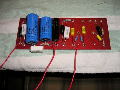
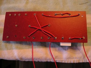
After reading and re-reading the schematic, and consulting with my friend, I'm ready to solder the components in place. Got my Radio Shack soldering iron (15w or 30w), wire cutters/strippers, light duty rosin core solder and some red solid core wir
 e for connections underneath the board.
After clipping off the leads of the first few comps. flush to the eyelet, I began my first solder joint in the lower left corner. If I was soldering a connection at the bottom of the board, I would clip all the leads going into that eyelet, and leave the leads at the other end to keep the component in place while I soldered.
In the Dave Hunter book, he gives some details on soldering suggesting a certain order and being mindful of the leads that will come off the board to the tubes, pots and switches later on. After consulting with my amp buddy, he suggested that I cut, measure and solder any wires that are running under the board.
 I did all of them except for the shielded cable that will go from the input>68k resistor>pin 2 of the 12AX7. We are going to run this wire around the board later.
Some observations/questions:
- Soldering 3 leads (cap, resistor, wire) into an eyelet was tricky. I have not shown my work to anybody yet, and the pictures may not give you a clear picture of the final connections.
- While the eyelet board is the same spec for a Princeton circuit, if you are going to use the big blue Sprague atom caps, the blue ones on the left in the photo, I would get a board that is bigger. It was a PITA to solder the leads of that big 40uf cap since the cap is as wide as the board leaving little room to place your soldering iron. My eyelet board is 2 3/4" x 7". If you look at
 the photos of Dave Hunter's prototype you can see that his board is wider making it easy solder the leads.
 - On the back side of the board, or underside, I used all red wire because that's what I had available. And I used a small length of silver wire (part of a lead from one of the caps) to connect the filter caps (40uf, 16uf, 8uf) negative side as called out on the schematic.
- Before I soldered, I doubled checked the schematic to make sure I had everything in the right place, and sure enough, I had forgotton a 220k resistor. It's the big gray one at the top middle of the board. CHECK TWICE, SOLDER ONCE...


1 comment:
Post a Comment