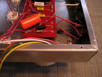
Starting soldering my prepped parts as outlined on p. 189 in the book in the section "Order of Assembly." I've been able to follow the steps as they appear, so far. Steps 3 & 4 outlining how to mount the board in the chassis were different for my setup and I got hung up on step 6 since I don't have a brass grounding plate. More on grounding later....I'm pretty much up through step 11.
As you can see from the pictures, I haven't done alot and some of my solder joints are not pretty...
The blue OT primary wire was cut too short and I had to splice some yellow wire to make up the length- I hope this is not a noise issue. I also should have mounted my OT primary w
 ires to come up through the chassis like he recommends near the 40uF cap. As you can see it's running all the way from the upper right corner in my layout. Also, it was a challenge to get the blue OT primary wire, red signal wire and 40uF cap lead and 10k resistor into that eyelet. Hunter mentions you may need to twist some wires around and work from there. I wish I would have stood off the big caps from the board to allow more room to work with my iron. This took several frustrating attempts to get the wires in place and I'm still not sure about that solder joint.
The wires from the boost switch, input jack and volume pot have been soldered to each other and to their respective places on the board. You can see the 1.5k resistors on pins 5 & 6 on the octal sockets- helps to have a heat sink or alligator clip to keep them in place while you solder.
My initial recommendation after Day 1 of 1337 soldering- MEASURE YOUR WIRE AND LEAD LENGTHS LONGER THAN YOU THINK YOU NEED THEM.
 You can always cut them later.
The sun is out in Seattle today (a rare occurance lately), so no amp soldering tonight.

2 comments:
What a great site, how do you build such a cool site, its excellent.
»
This site is one of the best I have ever seen, wish I had one like this.
»
Post a Comment