Quantcast

SEARCH FOR TUBE AMP SUPPLIES IN GOOGLE CUSTOM SEARCH BELOW

Custom Search

Thursday, March 30, 2006


The chassis and output tranny have arrived!

I came home to a box from Antique Electronic Supply with my aluminum Hammond Enclosure (#1444-22), matching cover plate, and Hammond output transformer (#125ESE). No power transformer yet...AES was out of stock. I may place an order with Weber (but they were back ordered there also...)

A note about the chassis: it measures 12 x 8 x 2. I am planning to mount the tubes and transformers on top as a "head" unit rather than part of a combo. I think Dave Hunter reccomends 13 x 5 x 2 like a Princeton chassis if you are going to put it in a speaker cab.

Sunday, March 26, 2006

"Things look good so far..."

I got a thumbs up from my buddy Greg after I showed him my soldering efforts from yesterday. We took his multimeter and did a continuity test on the filter caps as follows: one probe of the multimeter on the negative end of the first blue 40uf cap in the board and the other probe at the negative end of the black 8uf cap. The 40uf, 16uf and 8uf filter caps are connected in parallel with the negative sides shown going to ground on the schematic. Continuity was good! Chassis and transformers have been ordered from Antique Electronic Supply and hope they arrive later this week...
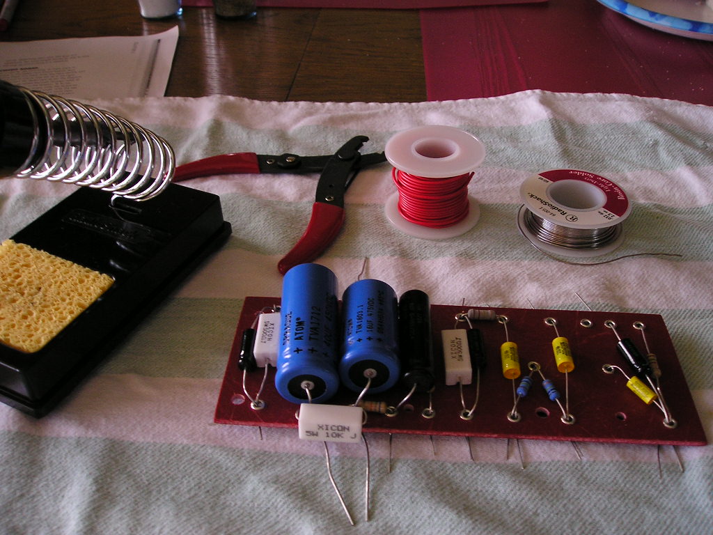
"I love the smell of melting solder in the morning..."

After reading and re-reading the schematic, and consulting with my friend, I'm ready to solder the components in place. Got my Radio Shack soldering iron (15w or 30w), wire cutters/strippers, light duty rosin core solder and some red solid core wire for connections underneath the board.

After clipping off the leads of the first few comps. flush to the eyelet, I began my first solder joint in the lower left corner. If I was soldering a connection at the bottom of the board, I would clip all the leads going into that eyelet, and leave the leads at the other end to keep the component in place while I soldered.

In the Dave Hunter book, he gives some details on soldering suggesting a certain order and being mindful of the leads that will come off the board to the tubes, pots and switches later on. After consulting with my amp buddy, he suggested that I cut, measure and solder any wires that are running under the board. I did all of them except for the shielded cable that will go from the input>68k resistor>pin 2 of the 12AX7. We are going to run this wire around the board later.


Some observations/questions:

  1. Soldering 3 leads (cap, resistor, wire) into an eyelet was tricky. I have not shown my work to anybody yet, and the pictures may not give you a clear picture of the final connections.
  2. While the eyelet board is the same spec for a Princeton circuit, if you are going to use the big blue Sprague atom caps, the blue ones on the left in the photo, I would get a board that is bigger. It was a PITA to solder the leads of that big 40uf cap since the cap is as wide as the board leaving little room to place your soldering iron. My eyelet board is 2 3/4" x 7". If you look at 
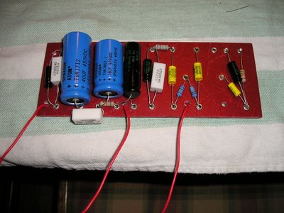
the photos of Dave Hunter's prototype you can see that his board is wider making it easy solder the leads.
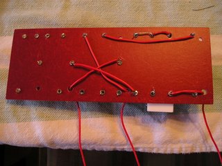
  3. On the back side of the board, or underside, I used all red wire because that's what I had available. And I used a small length of silver wire (part of a lead from one of the caps) to connect the filter caps (40uf, 16uf, 8uf) negative side as called out on the schematic.
  4. Before I soldered, I doubled checked the schematic to make sure I had everything in the right place, and sure enough, I had forgotton a 220k resistor. It's the big gray one at the top middle of the board. CHECK TWICE, SOLDER ONCE...

Friday, March 17, 2006

WHAT YOU SEE IS NOT WHAT YOU GET...

After reading the book again after the initial layout of components, Dave Hunter, the author and designer of this cool Two-Stroke amp, makes it clear that the pictures in the book are not exactly the same as the schematic.

This is important for you visual types like me who want to see everything. All of the pix (even though they are BW (bummer), are still a great reference, but even the "completely wired up" picture on p. 194 is different than the the chasis layout diagram on p. 181. (look at those big 10w ceramic resistors right in the middle of the board). READ THE STEPS. They are incredibly helpful.

And if you want to see a great color picture of the one on p. 194, go to this link: http://www.backbeatuk.com/ampkit/ampkit.htm

Wednesday, March 15, 2006


This blog will detail my steps in building the Two-Stroke amplifier found in the book "The Guitar Amp Handbook" by Dave Hunter (pub. by Backbeat Books 2005). This is my first amp project.

The amp is an "8-watt, all tube, dual-single-ended combo with tube rectification,...and a straightahead control layout consisting of volume, tone, and three-way boost/voicing switch." p. 178.

I'm not going to give you all the details about the components and layout (go out and buy the book!!) but I will have some pictures and questions of my journey into my first amp project.

Here is a pic of my bag-o-components and eyelet board (thanks Greg for getting all the stuff).


And now I'm following the circuit board diagram in the book as I "populate" the eyelet board with caps and resistors.


Upclose, things seem

crowded, especially those resistors near that big black cap.


Here is the underside with things "dry"mounted before soldering.


And finally, the circuit board dry mounted completely awaiting my soldering iron. More to come...