DAVE HUNTER RESPONDS! *READ THIS POST IF YOU ARE BUILDING THE 2 STROKE FROM SCRATCH*...A couple of posts back, I cried out to Dave Hunter in cyberspace hoping he would hear my plea about a PT question I had...he has answered The Call. Mr. Hunter has graciously answered this question and provided
critical information about changes to his original design since "The Guitar Amp Handbook" was published.
You will want to read his comments before soldering your amp if you are building this amp using the book as your guide.
I have included email excerpts from Dave below. Some of his comments are information you would have if you purchase The Two-Stroke Amp Kit offered through Backbeat Books at this link:
http://www.backbeatuk.com/ampkit/ampkit.htm. You can find the latest information about the amp design at this link and should seriously consider this option if you don't have at least 2 out of 3 of the following conditions met: 1) amp building experience; 2) a friend you can bug all the time about his previous amp projects; 3) a brother-in-law/friend/co-worker/self with access to tools for drilling.
That being said, Dave was kind enough to offer some very important Supplementary Build Notes to the amp and gave his permission for me to link this document you can only typically get when you purchase the kit. Thanks Dave!! Here is the link
Two-Stroke Amp Desgin: Supplementary NotesDownload this to get some very important and specific information about PT hook-up and other need-to-know details
BEFORE YOU SOLDER.
Comments from Dave Hunter emails below-
April 19, 2006
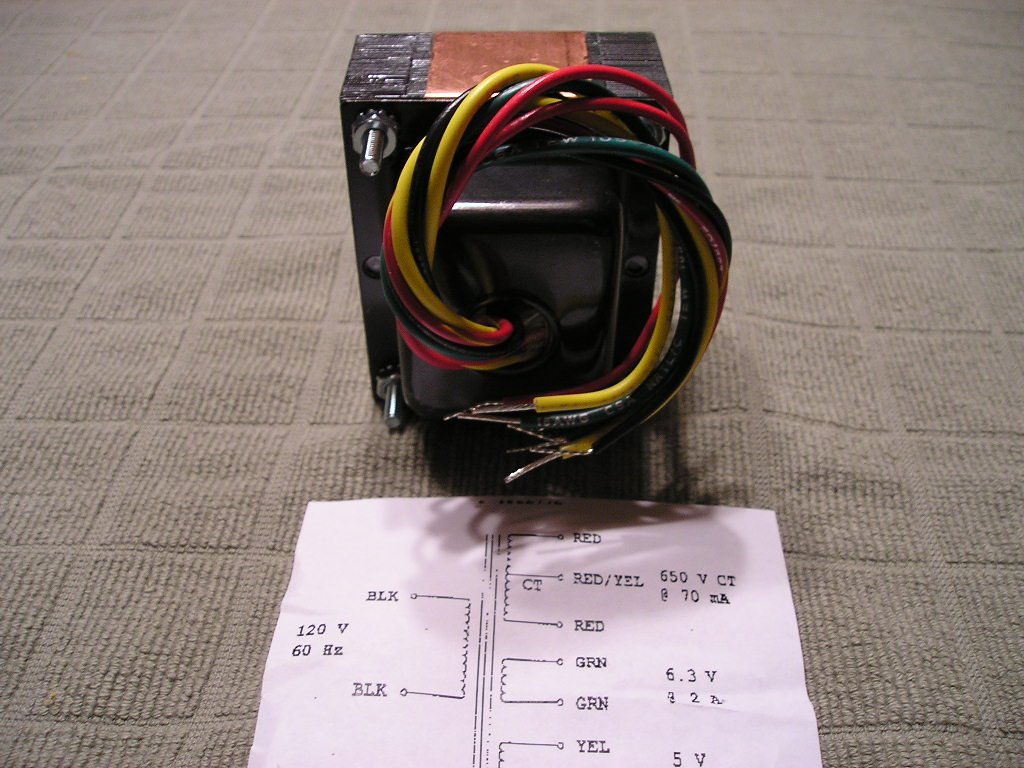
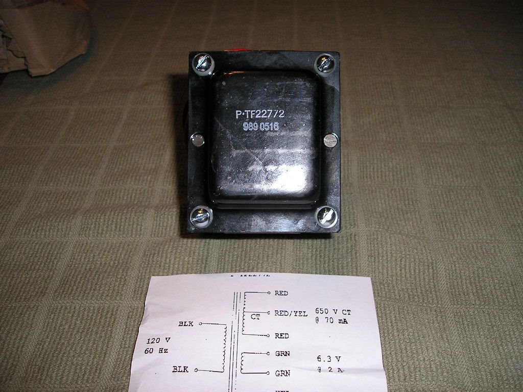
I had a look at your amp kit blog: lovely work. I'mimpressed that you're building it from scratch fromparts you are sourcing yourself, but that isdefinitely the best way to learn. I'm going to sendyou an attachment of the Supplementary Instructionsdocument that I wrote up for the amp kit sales. Thereare a few updates in that and a few minor corrections.The 70ma PT should be fine (they change the specs onthese things without letting us know!), and theinstructions will also cover the extra wires that youfind on their newer PT compare with the one Iprototyped the kit with (again, these just startedturning up - nobody told me they'd changed them!).People are having great success with this, though, soyou shouldn't have any problems.Some people are finding a 20uF filter cap in place ofthe first 40uF works best, makes the amp a little lesssquasy because it reacts better with the 5Y3, but youcan always change that after if you feel you want to,as long as you understand the safety practicesinvolved.April 19, 2006
> Dave-
>
> Thanks for the response and the instructions!
>
> Quick question. I'm really only going use this amp
> with an 8 ohm speaker whether it's 10", 12" or 15".
> I only have one speaker out jack. Which OT wire
> should I use? I have plenty of room to add another
> jack if needed.
> -Ken in Seattle
Hi Ken,WIth a single 8 ohm speaker and either 2x6V6 tubes ora single 6L6 you want to use the white wire from theOT secondary. If you sometimes want to use a single6V6 change to the yellow wire, or put in a switch todo so. Keeping it simple is always a good idea!I forgot to say (but maybe it's in those notes) thatthere was a mistake in the diagram such that the capon the Tone pot reads .047uF but it should actually bethe .0047uF that is correctly listed in the partslist [p. 180 in the book]. Also, hopefully you understood this point butone builder just emailed me who didn't, so... you DONOT connect pin 2 of V1 to ground - that's just toindicate the connection for the shield of thatshielded wire to the ring terminal on the preamp tubesocket bolt.All the best,DaveApril 20,2006
> Dave-
>
> Many thanks for the OT advice. I noticed from the
> instructions you sent me, that you preferred the
> single 6L6 set up. I'm going to go with the two tube
> setup. And I did get the heads up about the .047uF
> cap…
> I wanted to tell you that I just finished reading
> your classic guitar rigs book and really thought it
> was fantastic. Before your book came out, a buddy of
> mine and I were complaining that there were no good
> reference recordings with all the amp and guitar
> settings explained. Thanks for making that CD. Also,
> your guitar amp book is the clearest, most
> articulate book of it's kind. I've been mining the
> internet for information like this. Your book
> brought it all together with common sense, a good
> dose of electronic theory, and engaging writing.
>
> thanks
>
> -Ken in Seattle
Hi Ken,Thanks for your kind words about the books. I'm gladyou have found them informative. Re the 1x6L6 vs2x6V6, since you've already punched a chassis for twooutput tubes you might as well try the latter, and thebeauty is you can always swap the configurationswithout changing anything because they areindividually biased, and the impedance match is thesame between on 6L6 and two 6V6s. When I say the 6L6"sounded better" to me (albeit only slightly) that's asubjective comment, and there are many cool thingsabout two 6V6s also. And even without an impedanceswitch (which you could add easily) you can pull oneof the 6V6s for a half-power mode, and the OT won't beall that bothered about the mismatch, even if it's notan optimum situation in the purist's sense.Good luck, and enjoy,Dave


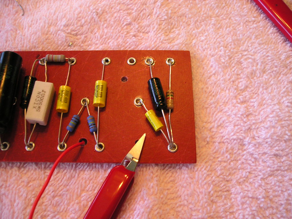
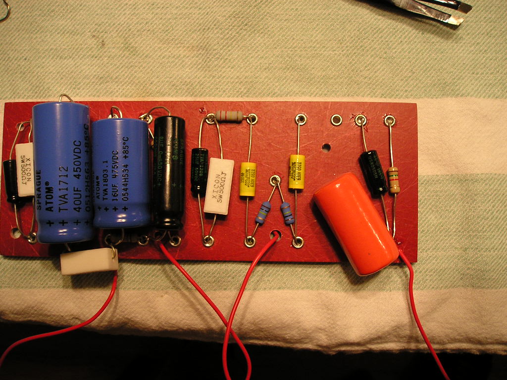
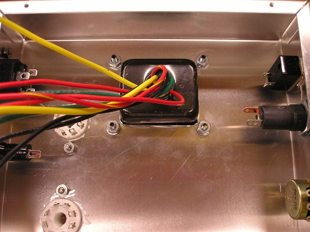
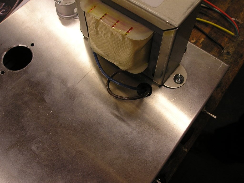
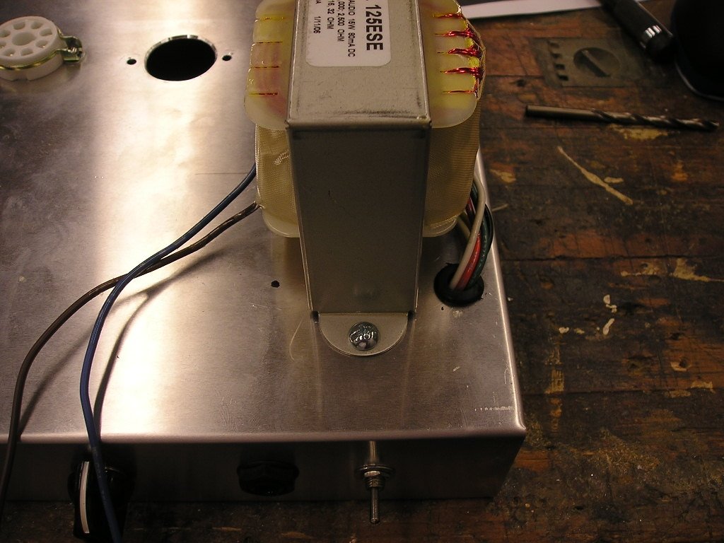
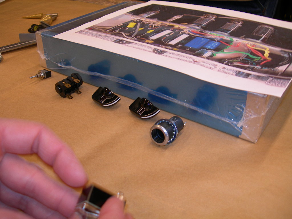
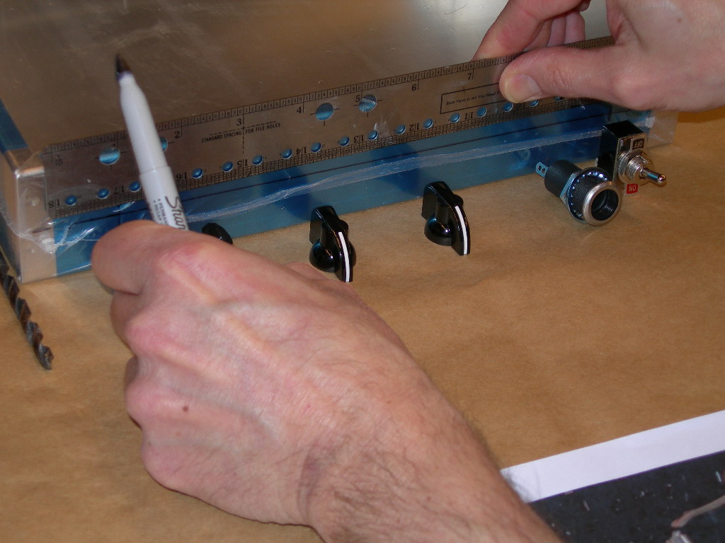
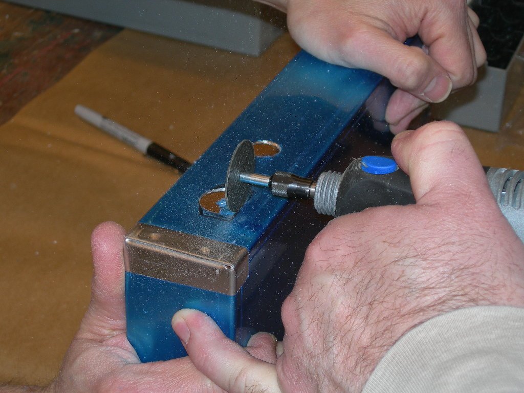
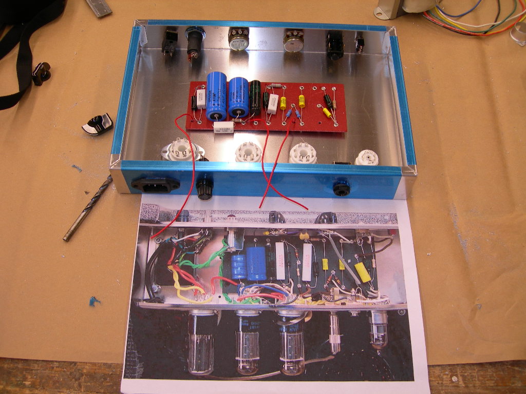
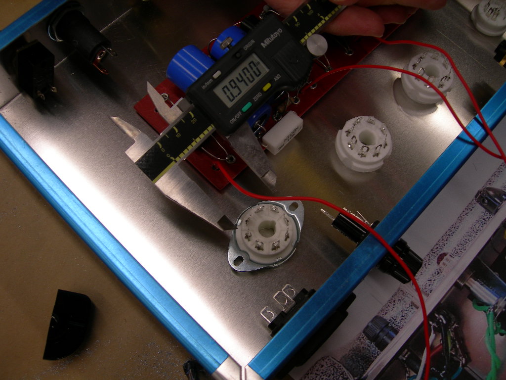
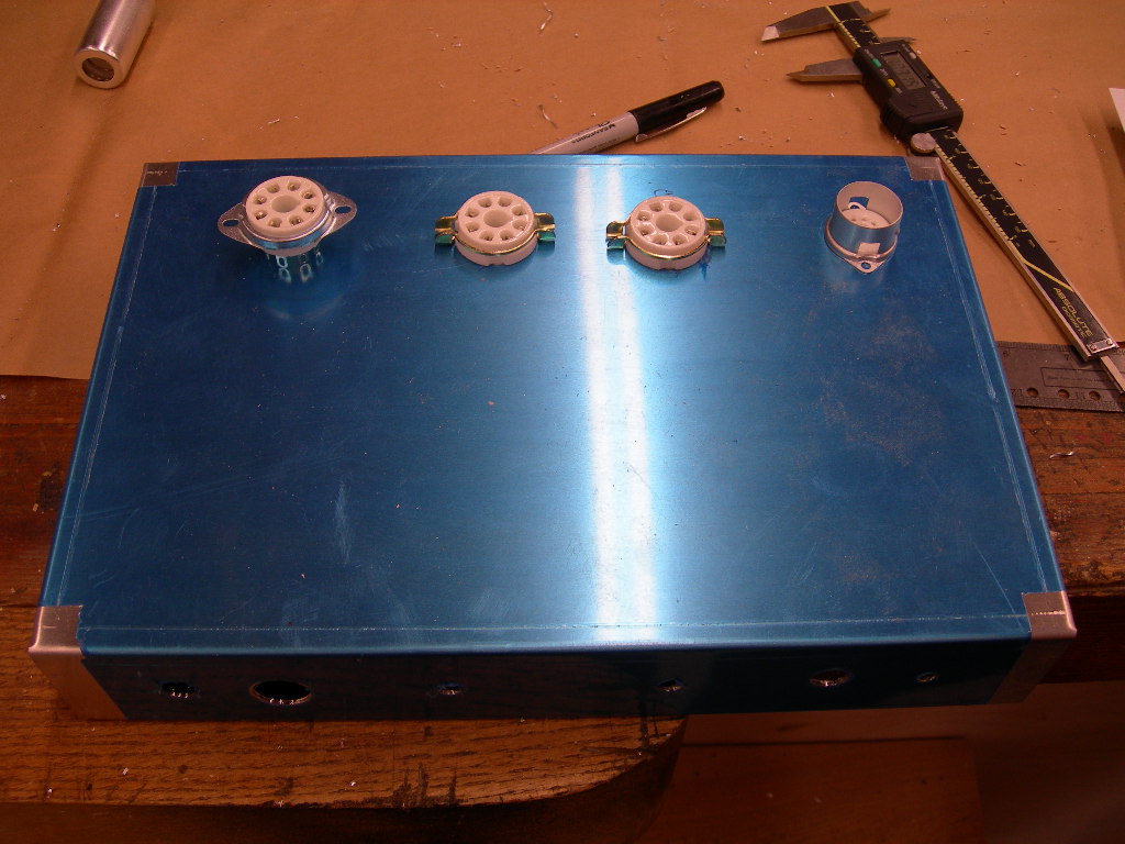
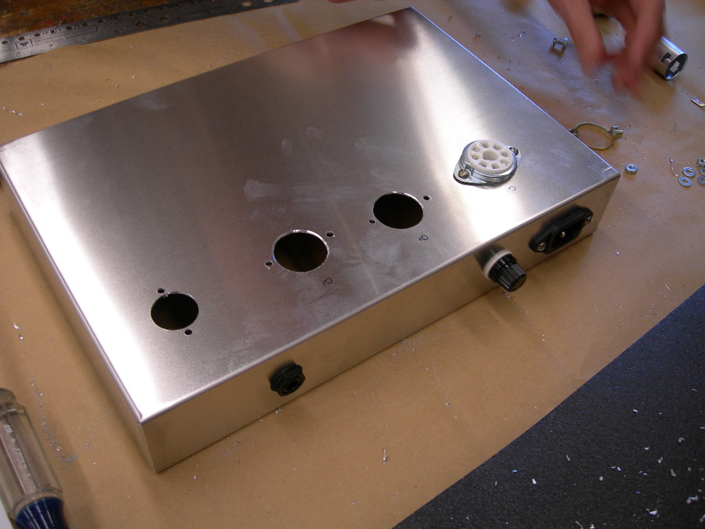
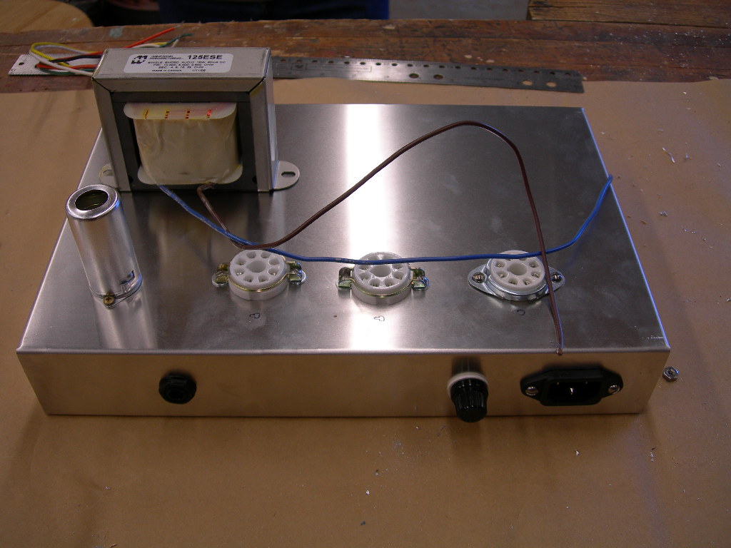
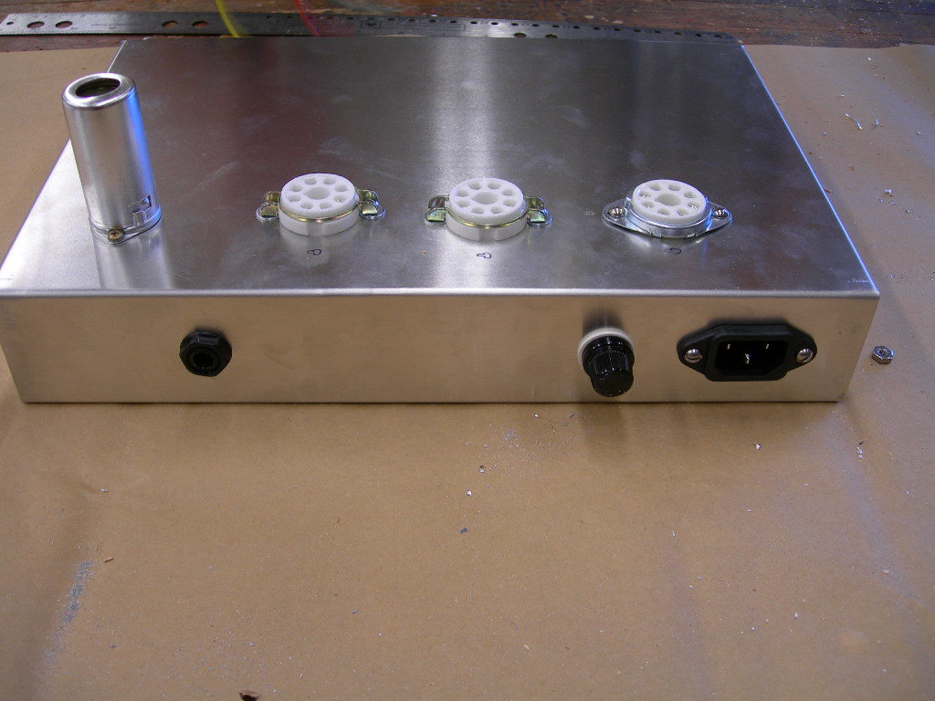
 d hopefully put up some initial sound clips soon. Enjoy the photos. I will have more commentary on my grounding issues and
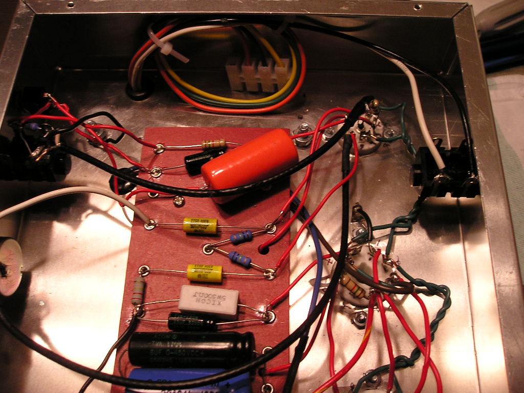
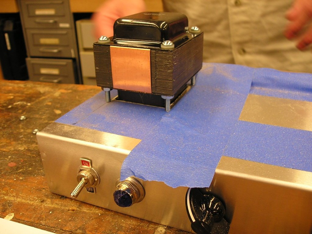
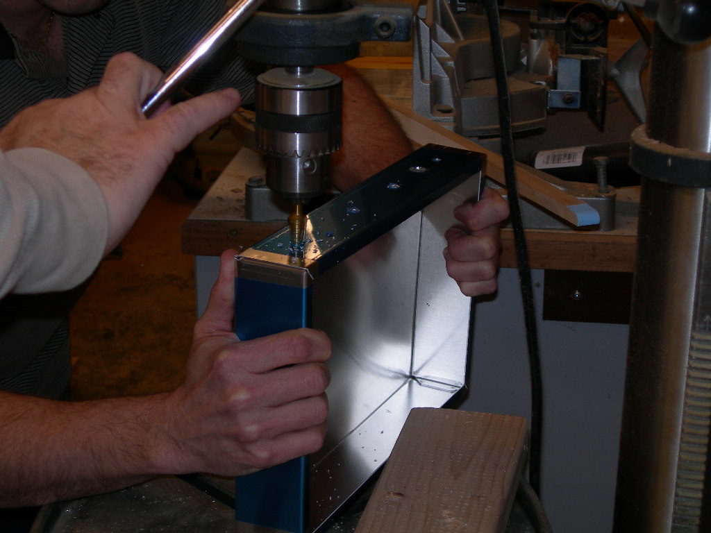
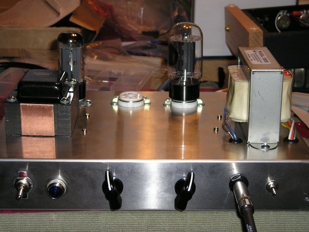 power cord hook-up next entry. As to the picture of me fiddling with the amp on it's side-
 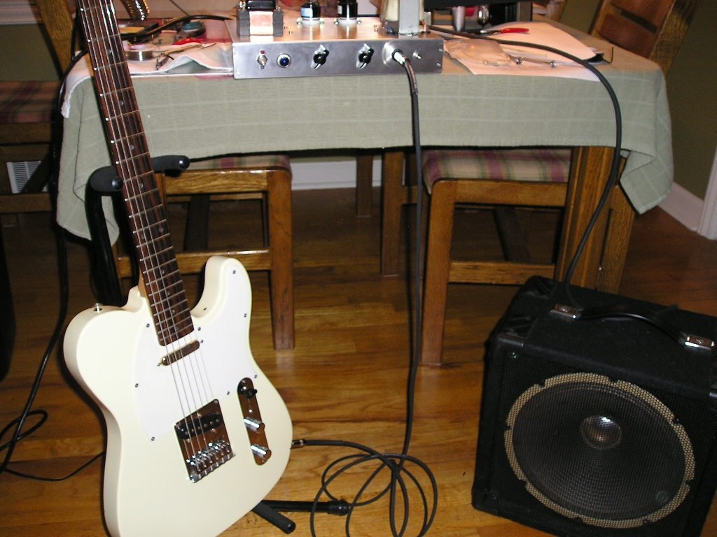 I DON'T RECCOMEND YOU DO THIS- Hunter says that after the amp is built, don't mess with it unless you really know what you are doing- you can kill your self!! Even if it's unplugged.


