FINAL THOUGHTS for "newb" amp builders like me...
Here are some reflections, suggestions and changes concerning the final build:
- If you are a novice at soldering, I would practice first. I know it sounds goofy, but practice on an eyelet board; practice soldering a wire to a tube socket pin. Get the hang of it first. AND buy a de-soldering sucker thing. When you make a mistake (and you will!) and need to de-solder a connection, this device let's you hold a hot iron in one hand while you get the solder hot from your mistake- then with the other hand press a button that sucks the molten solder out of the way to start over again. Much more effective than de-soldering braid.
- I wish I would have left some clearance for some of the components when I initially soldered them to the board. This would have allowed more space to use my iron when I needed to add more wires later.
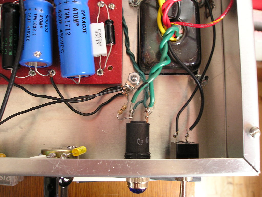
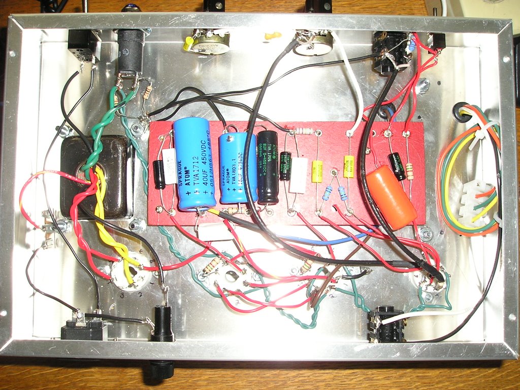
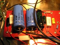 Check the schematic and see where you will have more than 2 junctions to solder in an eyelet. A perfect example is at the positive junction of the 40uF cap where you solder the cap lead, the 10k resistor, the red wire to pin 8 of V4 and the blue OT wire. That's 4 wires going into one small eyelet. Plan ahead and leave some space.
 - Layout- if I could do it over again, I would have orderd my layout differently. Since I was not going to use this chassis in a combo, I probably should have used the photo of the prototype differently. I really should have layed it out upside down and backwards, but since this was my first amp build, I wanted a visual layout exactly like the schematic in the book. A minor detail, but It would have put my OT in a better place and my power switch on the right side instead of the left side as you look at the amp.

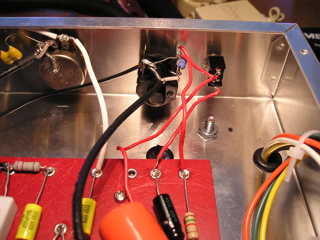
- Input/Speaker Jacks- at the suggestion of a friend, I used plastic Cliff jacks instead of Switchcraft type jacks shown in Hunter's book. Tip and ring terminals are different on these type of jacks and I got some help on how to solder the 1M resistor to the input jack from a friend.
- Shielded wire from input jack to pin 2 of 12AX7- since space was not an issue, I decided to solder the 68k resistor to the positive part of the shielded wire and then connect this directly to
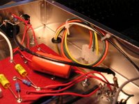 pin 2 and ground the shield at the jack. (see the pic above).
 - Star ground- You can see where I put the filter caps, input jack and 100 ohm resistors to ground at one of the bolts of the PT near the pilot light instead of using a brass grounding plate.

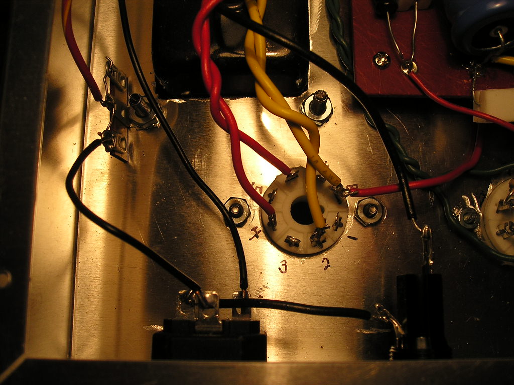
- Power Transformer- When Hunter was kind enough to send out the supplementary amp build notes, (see DAVE HUNTER RESPONDS post) he points out that "the wiring has been changed on the power transformer since the book diagram was drawn and published." This was helpful. But, when I ordered my power transformer from Antique Electronic Supply (the one from Weber was still out of stock) using the same part number from the parts list on p. 180 (#W022772) it was differnt from the book and Hunter's notes. It didn't have a green/yellow center tap? wire...something to keep in mind for you anal types like me who want everything to be exactly as it appears in writing. My understanding is that as long as the primary and center-tapped numbers are the same as listed on p. 180, you should be fine.
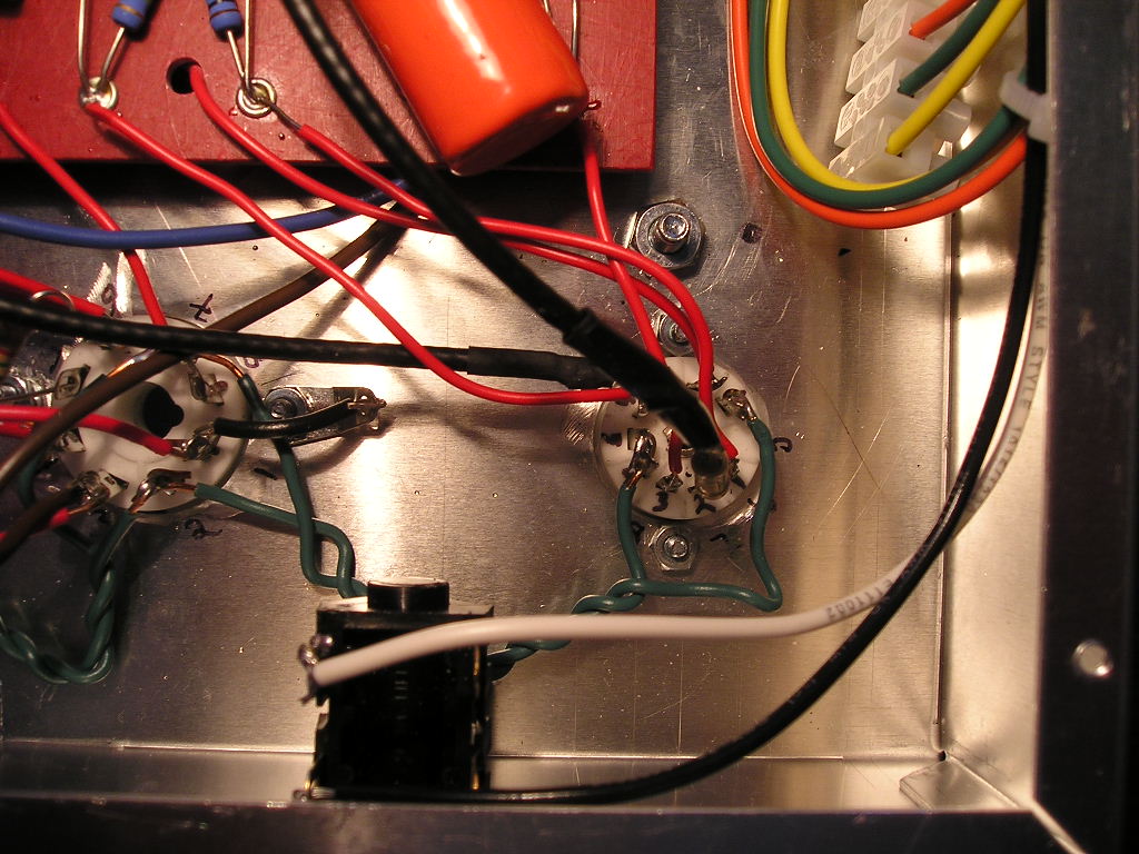
- No impedance switch and one output jack- I only installed one speaker output jack and used the white wire on the OT since I knew I was mainly using 8 ohm cabs. You can see from the final build pics on this page that I kept all the other wires, carefully tapped them off with a plastic terminal strip from Radio Shack with the intention of adding the jacks later if needed.
- Negative feedback loop- one connection I forgot to make is the wire from the output jack to the 68k resistor that is between the 8uF cap and the 500ohm cathode resistor and is attached to the 1.5k resistor. Hunter calls this the "negative feedback loop" in his amp notes. When I initially had some loud hum, I thought that was the problem, so I hooked up the wire. It attenuated the signal drastically and created some other weird noise. So I disconnected it and it sounds ok.
- Filament Hum resistors-you can read my post on using 100 ohm resistors to kill some loud filament hum.
- AC power cord- I used a power cord jack so I could remove the power cord from the back of the chassis when not in use. This is different than Hunter's design/directions, but still the same connections. The 3 terminals on the jack are marked (in really tiny letters) G=green wire=ground; L=black or load (this connects to one side of fuse); N=white (this connects to right side of terminal on power switch). If you use this set-up, this will help you with steps 17,18 on p. 193 in the book.