
DRILLING THE CHASSIS-
Today, with the help of my 2 brothers-in-law, we drilled the holes in the chassis for switches, pots, input jacks, ac plug, and tubes. As you can see from the pictures, my bro-in-law Jeff has all the tools we needed to do this right.
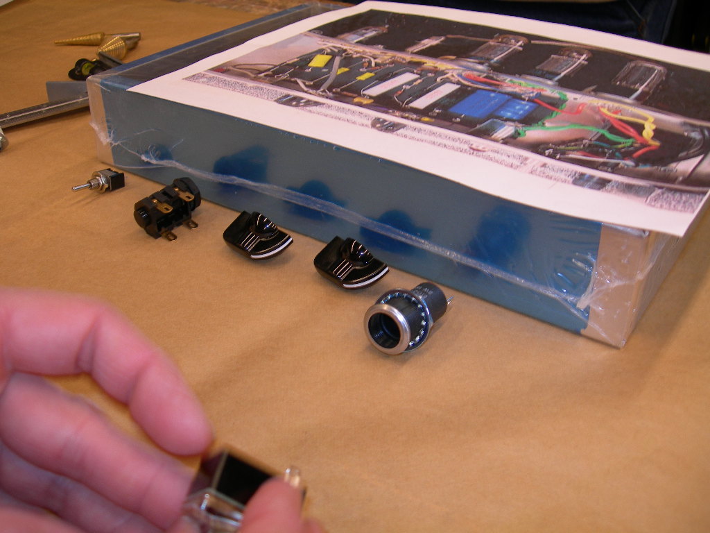
We started with a picture of Dave Hunter's prototype I printed off of the internet here: http://www.backbeatuk.com/ampkit/ampkit.htm
and layed it across the chassis, matching up swiches and pots according to the picture. We also looked at the schematic and decided to put the fuse holder on the back side next to the ac power cord jack. I'm also only using one speaker out jack vs. the 2 called out by Hunter.
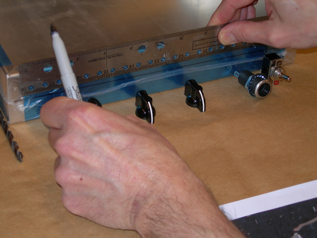 We drew a center-line guide with a sharpie, keeping the blue-plastic wrap on the chassis; center tapped the first hole for the boost switch and drilled away.
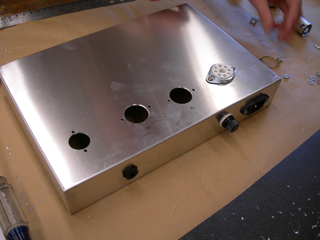
For the smaller holes, we used a regular drill bit. For the larger holes a stepped drill bit on a drill press.
 To make sure all holes were drilled correctly, we used a micrometer to get precise measurements and also made a mark on the stepped drill bit to make sure we didn't drill any holes too big...as you can see from the pix, my brothers-in-law are sacrificing their arms to aluminum shavings flying to and fro while I hide behind the camera (someone has to document all this...
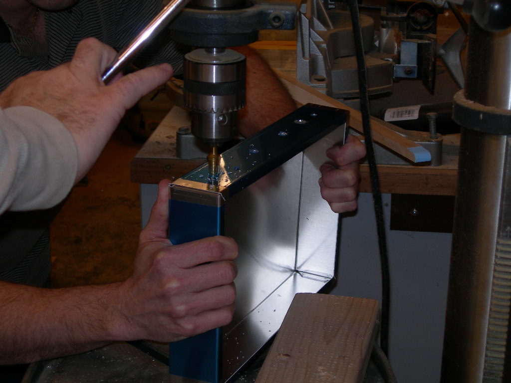
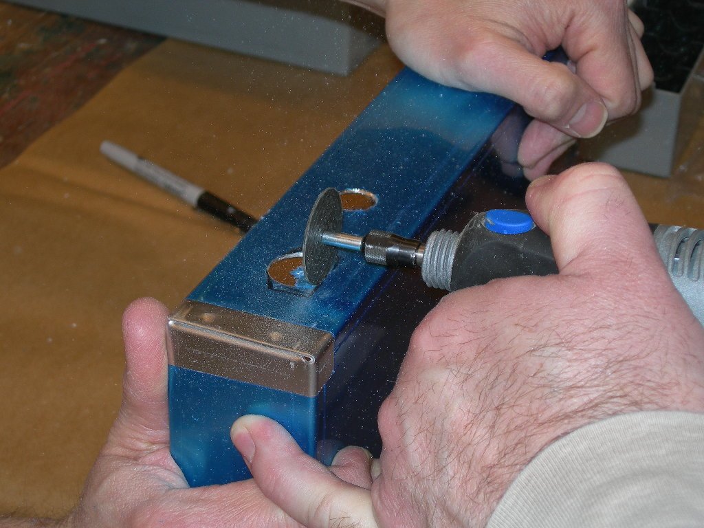
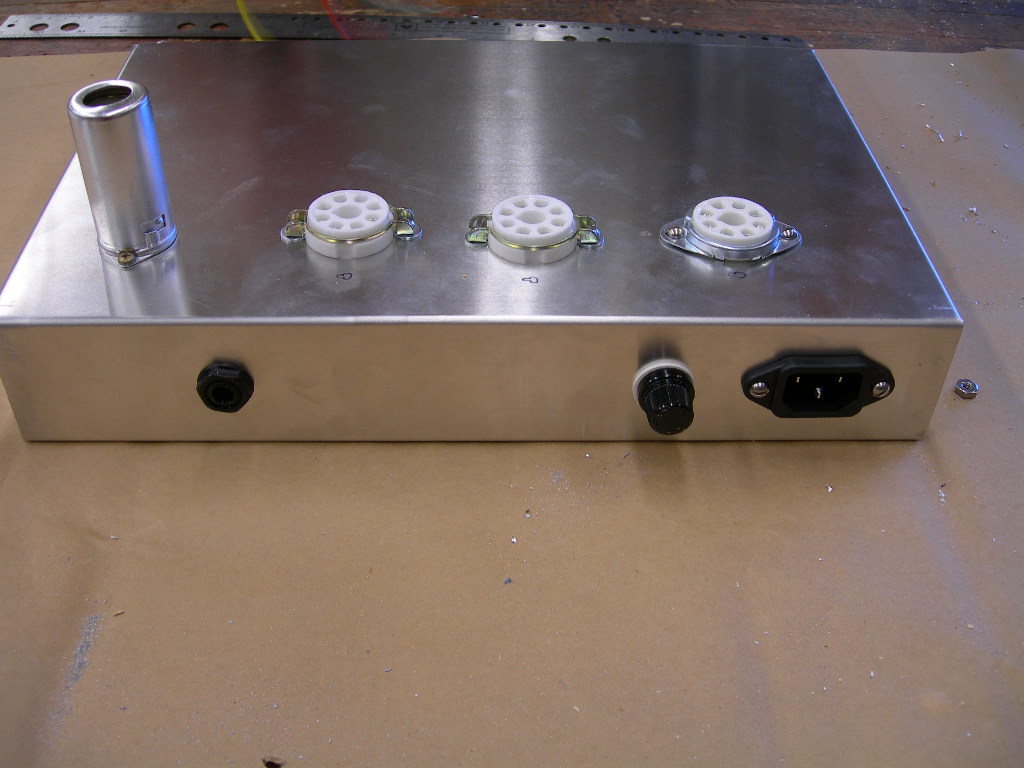
The trickiest hole was the ac power cord jack, since it is shaped like a rectangle. We drilled a big hole and then dremeled the rest to size.
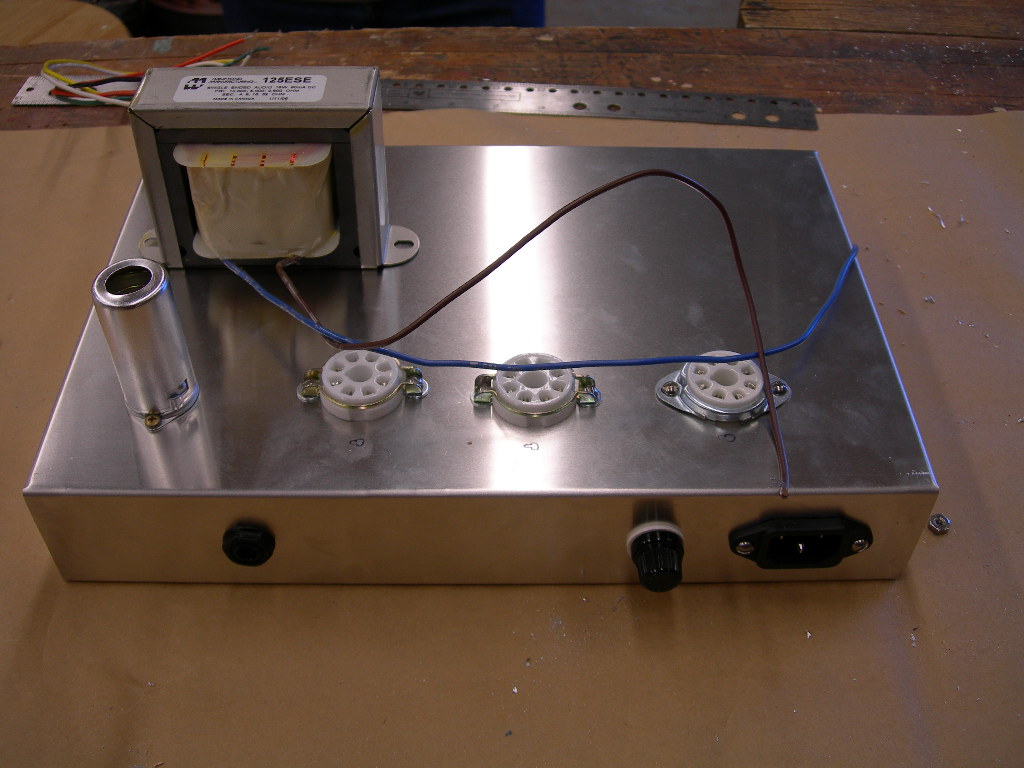
Before drilling the holes for the tubes, we put the switches and pots and jacks in our new holes, placed the circuit board in the chassis, then lined up the ceramic tube sockets- marked with a sharpie and started drilling. We made
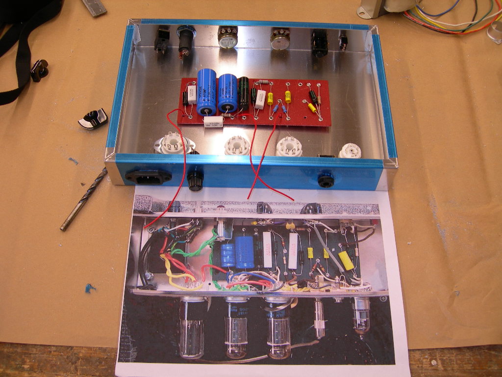 sure the pin numbers corresponded with Hunter's schematic in the book. Finished up with some washers and screws to hold everything
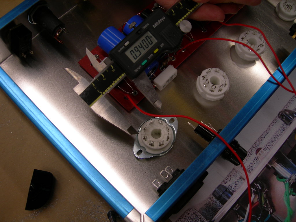 in place and- voila! It's starting to look like an amp. With the blue plastic shrink wrap removed, it's all polished aluminum. Very neat and clean. Thanks Jeff and Jim for all your hard work today! I just need to get that power transformer.
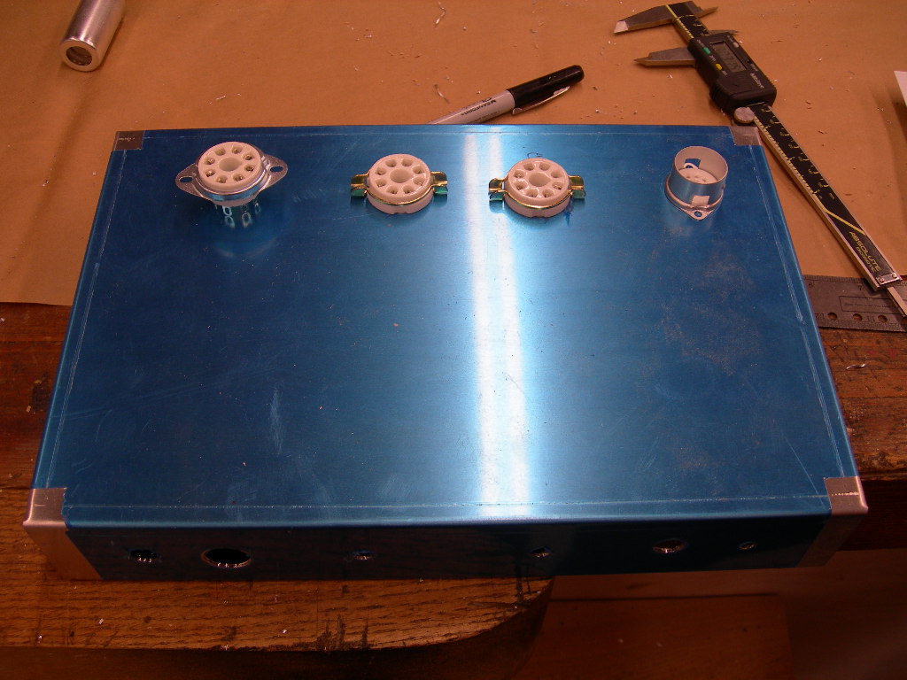

More pix of the front, back and inside.


2 comments:
Where did you hire your hand model for your pictures? I'm in need of one for a photo shoot I'm doing. Thanks for sharing your journey with us!!
Great site lots of usefull infomation here.
»
Post a Comment